Emilio M. Morales CE, MSCE, F.ASCE, F.PICE, F.ASEP 1]
Mark K. Morales CE, MSc 2]
ABSTRACT: Geophysical methods are generally non-invasive or non destructive methods long used in the construction industry for investigation of the subsurface. Principally, these are used for the detection of geologic anomalies such as cavities and voids, detection of buried pipes and other utilities, detection of water bearing aquifers for well development, exploitation of quarries and in determining soil stratification or layering. In addition, the methods provide a means for verifying as constructed pavement thicknesses in a continuous unbroken image of the pavement structural configuration or determining rebar embedment and layout non destructively.
The use of Geophysical methods confers advantages as they generally speed up the process of investigation, provide continuous streams of information not otherwise available in discrete sampling or invasive procedures and give advance information on what to expect for a given locality before a more detailed and costly soil exploration is even planned. Thus Geophysical methods are a force multiplier for the engineer and allow the user to identify potential problem areas or target areas even before the start of a detailed Soil Exploration program.
Geophysical methods are not a replacement to a detailed soil exploration program; rather they augment these programs to yield more meaningful and area extensive but more intensive information at the fraction of the time and cost.
The Paper discusses three general methods which have been employed by the authors in various projects. Case histories are discussed to highlight successful deployment of these methods in the Construction Industry.
1.0 INTRODUCTION
Geophysical Methods have been around for quite some time. These are non invasive procedures employed in order to determine subsurface soil conditions and geologic anomalies such as cavities and voids or buried objects such as pipelines. Geophysical methods are used for various purposes in Civil Engineering Investigation of the subsurface.
The advent of high speed computers and fast signal processors have vastly improved the technology and resulted in increased reliability and signal clarity in the use of these methods.
This Paper presents our local practical experience in the deployment of Geophysical methods and equipment to address and provide solutions to various practical problems3 where conventional approaches may not give adequate information or may not provide it in a faster or more accurate way. Although Geophysical methods address the need for more information compared to conventional borings, these are not substitute to actual soil borings particularly when soil design parameters (strength and compressibility) are needed. However, borings may provide only limited discrete information points or are limited because of budgetary restrictions while Geophysical methods may provide a continuous data stream or even three dimensional images of the desired target of interest. Thus these two methods are complementary and would provide a more meaningful information record when done together or when augmented by each other.
Although again these methods are not a substitute for detailed borings except for specific objectives which do not require strength characterization or design strength or compressibility parameters, they can sometimes yield more meaningful results and thus corroborate results of other methods.
2.0 GROUND PENETRATING RADAR (GPR)
Ground Penetrating Radar Technology is an offshoot of the military use of radar and was spurred by the need to do research in the thick ice of the Polar Ice Cap4 which would be difficult to investigate continuously by borings. The developed technology is now used widespread in the construction and civil engineering profession but has now also reverted to military use again in the detection of buried mines (IED’s) and arms caches particularly in Iraq and Afghanistan.
Electromagnetic radar impulses (EMP) are transmitted at a frequency of 100 to 200 kHz from the equipment and are bounced back or absorbed by objects depending on the material stiffness and saturation and other interferences. A receiving antenna receives the bounced signals or pulses and is processed by computer in Real Time to provide a computer image of the subsurface.
The choice of Ultra magnetic Impulse Frequency determines the effective depth for exploration. The Frequency is inversely proportional to the effective depth of exploration. Very high Frequencies are used for shallow depths such as for roadway pavement structure investigation where a continuous record of the pavement structural thickness to the nearest millimeter is desired for dispute resolution or for QA and audit purposes.
3.0 GPR APPLICATIONS
- Used for detection of Cavities and Geologic Anomalies
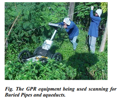
- Used for detection of Buried objects such as pipes, Improvised Explosive Devices (IED’s) mines, subsurface disturbances and Archeological artifacts
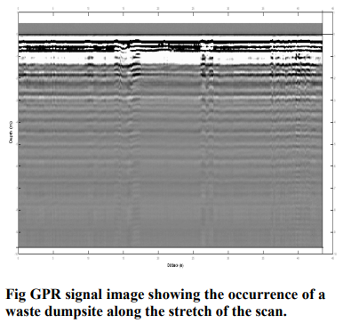
- Used for environmental scanning to determine waste landfills
- Used For determination of structural thickness of Roadways and pavements
- Used for detection of Rebars and other embedded Objects in Concrete
4.0 INHERENT LIMITATIONS OF GPR
The presence of highly saturated plastic clays would tend to mask the radar signals and may produce no radar image at all or very hazy ones leading to some inaccuracies in the procedure. In addition, the presence of surface obstructions such as concrete pavements, the presence of subsurface boulders and other objects would tend to affect the accuracy of the signals and the images generated for low antenna frequencies.
In highly conductive zones, such as saturated montmorillonite clays or saline marshes, it is almost impossible to obtain useful results below 1-2 wave lengths of the antenna.5
However, the beauty of these different Geophysical methods is that the other individual procedures can complement for the weakness of the other. As in the above example, the inability to penetrate highly saturated clays can be overcome by augmenting this with the use of Seismic Refraction methods. Also, the weakness or inability of Seismic refraction methods to penetrate denser materials overlying softer or poorer layers is completely overcome with the use of GPR.
Therefore, the complete lineup of equipment could offer a comprehensive solution by overcoming inherent limitations of one method and augmenting this with the strength of another method.
5.0 GPR APPLICATION CASE STUDY
An Industrial complex was planned for construction. Subsequently, we were asked to undertake Geotechnical investigation with numerous borings.
The Borings indicated to us the presence of what originally were suspected to be cavities in the karstic limestone formation in the area which are not uncommon in these formations.
Further studies and additional boreholes indicated that the cavities were interconnected and the alignment was correspondingly traced in the boring plan. Subsequent inquiries with adjacent property owners indicated that these were fortune hunting tunnels oriented towards the main facility. We requested additional confirmatory borings to trace the tunnel alignment as well as the suspected vertical access shaft which extended as deep as 25 meters below the NGL and which consisted of very loose to loose backfill material. This request was granted and six additional boreholes were made and confirmed the presence of tunnels in the area.
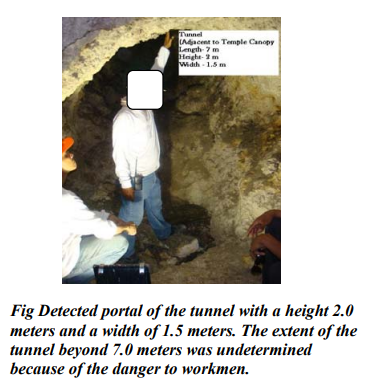
No attention was paid to it by the owners immediately due to the hectic schedule and because the tunnels were deep, until very late in the construction when a tunnel portal was detected during the excavation for a large diameter drainage line very close to the main building which was already completed.
We were requested to verify the extent of the anomaly by GPR.
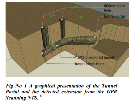
Our investigation confirmed the original alignments of the “cavities” which turned out to be fortune hunting tunnels, burrowed under the main building footprint. It turned out that the site of the main building was the original Headquarters and residence of the commanding General of the Japanese Imperial Air Force overlooking a major airfield.
The Tunnel alignments including the recent discoveries were plotted and subsequently verified by large diameter auger equipment.
What was detected coincided with our predictions as extrapolated from the initial soil borings.
GPR sweeps or scan lines were requested in areas under building footprints and were not required in the open areas. The GPR survey confirmed the initial results from borings and also extended the detected tunnel extensions beyond the initial influence areas of the previous borings.
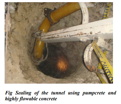
The tunnels were finally sealed by highly flowable concrete. In one area, it took 7 Transit mixer loads to seal one segment of the tunnel.
One other segment which collapsed could not show a positive indication but when the hole was pumped with water, the water intake was very significant.
Subsequently this segment was also sealed by highly flowable concrete.
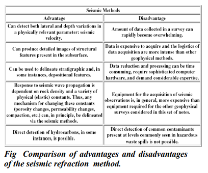
6.0 SEISMIC REFRACTION METHODS
Seismic refraction consists of sending shock waves into the soil either by use of hammer striking a steel plate or with the use of explosives.
The vibrations induced are picked up by a Seismograph through an array of geophones which pick up the refracted and reflected signals. The velocity and travel time for these shock waves through materials with varying material stiffnesses are measured and the refracted and reflected signals are processed by an on board computer, as they travel to various media .
A Seismic Refraction Layout is typically known as a “Spread”.
Each spread consists of 12 to 24 Geophones as used in shallow engineering surveys.
A “shot” is an initiation of a shock wave into the surface of the soil to initiate the recording of the arrival times of the shock waves at various Geophone locations.
Each shot would provide information of the underlying soils under typical conditions.
Several shots are needed to ensure that geologic anomalies are detected such as sloping bedrock, faulting, presence of cavities etc.
A typical spread would require a minimum of five “shots “ to determine the characteristic stratification of the subsoil and the underlying physical properties in terms of Seismic Velocities.
7.0 CASE STUDY APPLICATION OF SEISMIC REFRACTION
An industrial complex wanted to expand on an adjacent elevated hill beside the Refinery. The new expansion of the plant will require a massive cut on this hill including through the bedrock.
The depth to bedrock is known to be
Highly variable and it would be required to plot the exact profile of the Bedrock at close parallel offsets in order to draw an accurate bedrock contour and quantify hard rock excavation. Due to the variable depth, volume of hard rock excavation cannot be accurately determined. It was estimated by the client that to do so using conventional subsurface investigation methods would involve at least 30 borings and would take 65 days to complete.
An accurate Bedrock contour is needed to quantify hard rock excavation, which need to be blasted by explosives.
Because of the large area involved, numerous boreholes would need to be drilled to characterize the bedrock contour. This would be very expensive and the time involved would delay earthmoving and hard rock excavations as the equipment were already mobilized.
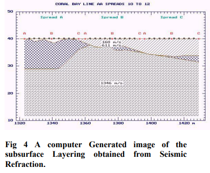
Seismic Refraction was requested and five Parallel lines consisting of 13 spreads each at 20 meter parallel offset lines were done. The complete operation was completed in one week and an additional week was needed for data reduction and interpretation in the office.
As a result, the bedrock contour was accurately delineated resulting in more accurate estimates of the cost as well as reduction in time to Project completion. As another added benefit, some of the week layers (lower velocity layers) were detected which would be amenable to ripping rather than blasting.
8.0 GEORESISTIVITY METHODS
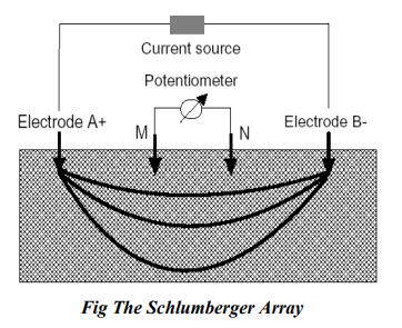
Georesistivity methods fall into the category of Vertical Electrical Surveys which sends electrical current into the subsurface. The resulting electrical resistivities are then measured and correlated and compared with various soil types and water bearing aquifers to yield layering or stratification information as well as identify other layer properties. Two commonly used methods are the Schlumberger
Electrode array (Shown below) and the Wenner Electrode array. The former method is more popular for use in well or aquifer surveys.
The Schlumberger Method 7
The Schlumberger array uses four electrodes: two of which serve as the current electrodes and the other two for potential electrodes. The current electrodes are represented by AB and the potential electrodes by MN. Electric current is introduced into the ground using AB electrodes and the potential difference is read using the MN electrodes. Initially, lengths of AB and MN are set to two meters and one meter, respectively. As the measurement progresses, AB expands from the sounding center at the spacing interval of factor of square root of two, i.e., 1, 1.4, 2, 2.8, etc., keeping the MN constant. However, as the length AB increases, electrical voltage drops considerably. The manufacturer of the instrument has prescribed a minimum voltage of five millivolts when conducting resistivity measurements. To keep voltage above the set minimum voltage, MN has to be expanded as well. In order to detect discrepancy for the reading when MN is expanded to a new length, duplicate readings are taken for the same AB but with different MN values.
Readings from the instrument are raw resistivity data. Actually, they are in the form of volt/current ratio, having a unit of “ohm”. These resistivity raw data are multiplied by a geometric factor unique for every set of AB and MN which is taken from the formula:
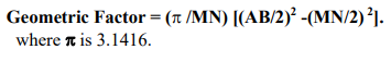
The resulting values when the readings are multiplied by this factor will now be the apparent resistivity. The usual field procedure is to plot the computed apparent resistivity at logarithmic scale paper to gain initial view of the resulting curve. This is undertaken prior to interpretation or at the sounding site to preclude unwanted curve, which results when errors are committed in readings and in distances set up.
The interpretation of the measured values is facilitated through the use of a built in computer software and signal processor within the instrument. Resistivity sounding interpretation software was used for database management and sounding interpretation including plotting of sounding curves.
9.0 CASE STUDY APPLICATION OF GEORESISTIVITY
An industrial plant had to boost groundwater capacity as the existing wells are proving inadequate.
It was originally suspected that the Existing wells would not meet future demands of the Factory.
The four production deepwells were barely adequate to meet the demands of the manufacturing facility although the deepwells are spaced far apart and not competing with each other. The wellscreens were set at the middle of a deep medium yield aquifer at approximately 200 meters below existing NGL.
The site was subjected to Vertical Electrical Survey (VES) using an Electric Georesistivity Equipment.
The results were very surprising, as the VES pointed to a shallow but otherwise very promising aquifer which was consistently bypassed by the previous deep wells drilled and resulted in a new program for Groundwater development to exploit the shallow aquifer which has remained an untapped groundwater resource.
The results of the VES pointed to a very promising highly permeable and very shallow water bearing layer which has been consistently bypassed in all the existing well developments. This shallow aquifer can increase the yield from these existing deep wells by using two well screen settings instead of one by at least 2.5 X.
Future well settings will concentrate on this shallow aquifer for major development.
The direction points to exploitation of this aquifer layer as well as the lower aquifer with a new well.
The potential total yield is around 50 to 70 cu meters per hour which could significantly boost the future water demand in conjunction with the other wells.
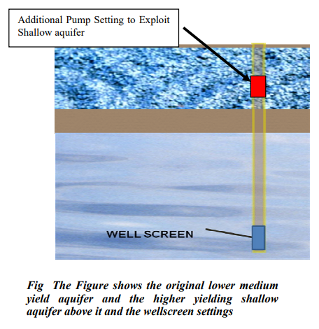
We do not expect significant impacts on the lower aquifer in terms of potential yield when exploiting the upper aquifer as the latter is separated by an impermeable clay layer or an aquiclude.
10.0 SUMMARY OF CONCLUSIONS
The usefulness of Geophysical methods has been demonstrated by several case studies.
It is expected that greater awareness by the Engineering Community will lead to increased deployment of these methods to solve Civil Engineering and other problems involving the subsurface.
The three methods discussed are in themselves complementary to each other and the limitations in one could be reinforced or strengthened by the other methods providing a full arsenal of procedures to effectively obtain cost effective and more meaningful results of subsurface anomalies and properties.
The Geophysical methods are not intended to supplant borings except in specific cases where information gathered would be sufficient to address the intended purpose/s.
It is hoped that through these practical sample applications, a better appreciation of the capabilities and cost effectiveness of each method can be understood better by the engineering community.
1 Principal, EM2A Partners, MS in Civil Engineering, Carnegie-Mellon University, Pittsburgh, PA. Fellow PICE, ASEP and ASCE, PhD Candidate Asian Institute of Technology, Bangkok Thailand, Formerly Senior Lecturer, UP Graduate Division, School of Civil Engineering, Diliman.
2 Managing Director, Philippine Geoanalytics Inc., Master of Science, University of California, Berkeley, Berkeley Ca., President PGA Earth Structure Solutions Inc., Lecturer, Mapua Institute of Technology, Department of Civil Engineering, Intramuros, Manila.
3 In all the practical case studies, the name/s of the project and the clients cannot be mentioned due to confidentiality issues. Project description and locations have been altered somewhat so as not to identify the Sources. Where credit is due, we apologize to the sources as we cannot name them.
4 Internet download
5 SEGJ. “Application of Geophysical Methods to Engineering and Environmental Problems”. Advisory Committee on Standardization, The Society for Exploration Geophysicists of Japan, 2004.
6 Computer graphics representation courtesy of client (un named).
7 From Internet Download
Download Geophysical Methods in Civil Engineering – Practical Applications